How-To Guides
Furnace Inspection Checklist (Detailed 2025)
AZparts Team
Updated on November 17, 2025
15 min read
A reliable furnace is key to keeping your home safe, warm, and energy-efficient. With this comprehensive furnace inspection checklist and downloadable furnace inspection form, AZParts helps both homeowners and technicians identify potential issues early—before they turn into expensive repairs. From safety checks to airflow testing, this checklist covers every critical step in maintaining peak furnace performance.

1. Furnace inspection checklist
1.1. Habitable room requirements
In areas where the average winter temperature drops below 60°F (16°C), every habitable room in a home must have a working heating system. The system should be able to maintain at least 68°F (20°C) at a point 3 feet above the floor and 2 feet from any exterior wall.
This applies to all rooms used for living, sleeping, cooking, and hygiene activities, as outlined in the 2018 International Residential Code (IRC R303.10).
1.2. Unsafe conditions
If there’s any indication of danger such as signs of gas leaks, faulty wiring, or structural damage, the system should be shut down immediately using the electric service switch. The homeowner or occupant must be informed. The local utility provider should be contacted for further inspection.
1.3. Inoperable system
Common signs of malfunction include the system not turning on, unusual noises, or blinking error lights visible through the unit’s sight glass. These error codes usually correspond to a diagnostic chart provided by the manufacturer and can help identify specific issues.
1.4. Understanding the sequence of operation
The system must follow this sequence to work efficiently and safely. Here’s how a typical gas furnace should operate:
- The thermostat calls for heat.
- The inducer motor turns on to start the airflow.
- Safety switches check for any problems.
- The ignitor (either a hot surface or spark type) activates.
- The gas valve opens, and gas flows to the burners.
- The burners ignite, and the flame is verified by a sensor.
- The heat exchanger warms up.
- The blower fan activates to circulate warm air through the home.
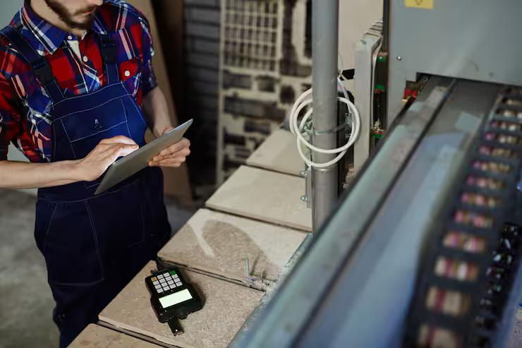
A basic inspection checklist for evaluating a gas-fueled central duct furnace (Source: Freepik)
2. Gas Furnace Inspection Checklist
2.1. Thermostat
Start by identifying the thermostat. The thermostat is the control point for the heating system, so it should be mounted in a central, accessible area where it can accurately sense the ambient temperature.
Inspecting the thermostat to ensure it is centrally located and accurately sensing room temperature (Source: Freepik)
2.2. Furnace Description & Location
A furnace must be easy to access for inspection, servicing, and replacement. There should be a clear passageway at least 24 inches wide with solid, continuous flooring.
If the furnace is in an attic or crawlspace:
- The access path must be at least 30 inches high and 22 inches wide
- The flooring must be at least 24 inches wide and no longer than 20 feet
- The access opening should be at least 20 by 30 inches
- In front of the furnace, there must be a 30 by 30-inch level workspace
According to building codes, furnaces should not be installed in sleeping rooms, bathrooms, storage closets, or spaces that only open into those rooms. Exceptions apply if the furnace is a direct-vent type or installed in a sealed room with a self-closing, weatherstripped door and outside air for combustion.
2.3. Furnace Category (I, II, III, or IV)
Furnaces are classified by how they vent combustion gases. Home inspectors typically encounter Category I and Category IV systems.
- Category I: These use metal Type B vent pipes, operate under negative pressure, and do not produce condensate.
- Category IV: These operate under positive pressure and produce condensation. They use plastic vent pipes (usually Schedule 40 PVC or CPVC) as specified by the manufacturer.
The venting system should always align with the furnace category and manufacturer guidelines. Proper materials must be used for safe and efficient operation.
2.4. Air Flow & Delta T
Though detailed Delta T testing is outside the scope of a home inspection, inspectors may reference the expected temperature rise listed on the furnace’s data plate. A typical range might be a 30°F difference.
- A high Delta T could suggest restricted airflow (e.g., dirty filters or blocked ducts).
- A low Delta T might indicate that the furnace is undersized or that airflow is too high.
If airflow seems off, further evaluation by a licensed HVAC technician is recommended.
If airflow looks restricted, consult a licensed HVAC technician (Source: Freepik)
2.5 Venting (Exhaust & Flue System)
While inspectors are not required to examine the interior of flues or chimneys, they should check the exterior surfaces of the venting system for corrosion, cracks, blockages, or signs of condensation.
- Vent connector pipes (Type B double-wall metal for Category I gas furnaces) should:
- Be properly supported and fastened every 4 feet.
- Slope correctly (plastic pipes should slope 1/4" per foot to drain condensate back to the furnace).
- Avoid passing through air ducts or plenums.
- Be insulated if running through unconditioned spaces
- Maintain minimum clearances from combustible materials:
- 1 inch for Type B
- 6 inches for single-wall metal
- Use a metal shield if insulation is present nearby
- Vents must terminate correctly:
- At least 1 foot above the roof if they’re ≤12 inches in diameter and at least 8 feet from a wall.
- With proper flashing and a listed cap.
2.6. Protective Barrier
If the furnace is located in a place where a vehicle could hit it (like an attached garage), a protective barrier must be installed to prevent damage.
2.7. Lighting & Electrical Receptacle at Unit
There should be a light fixture and an electric receptacle near the furnace to allow for safe servicing and inspection. These must be easy to access and in working condition.
2.8. Disconnect & Emergency Switch
- An electrical disconnect switch should be installed at or near the furnace. Inspect the furnace switch, the box, the cover plate, and wiring for any damage or wear.
- An emergency shut-off switch may also be installed at a safe distance in case of dangerous conditions near the unit.
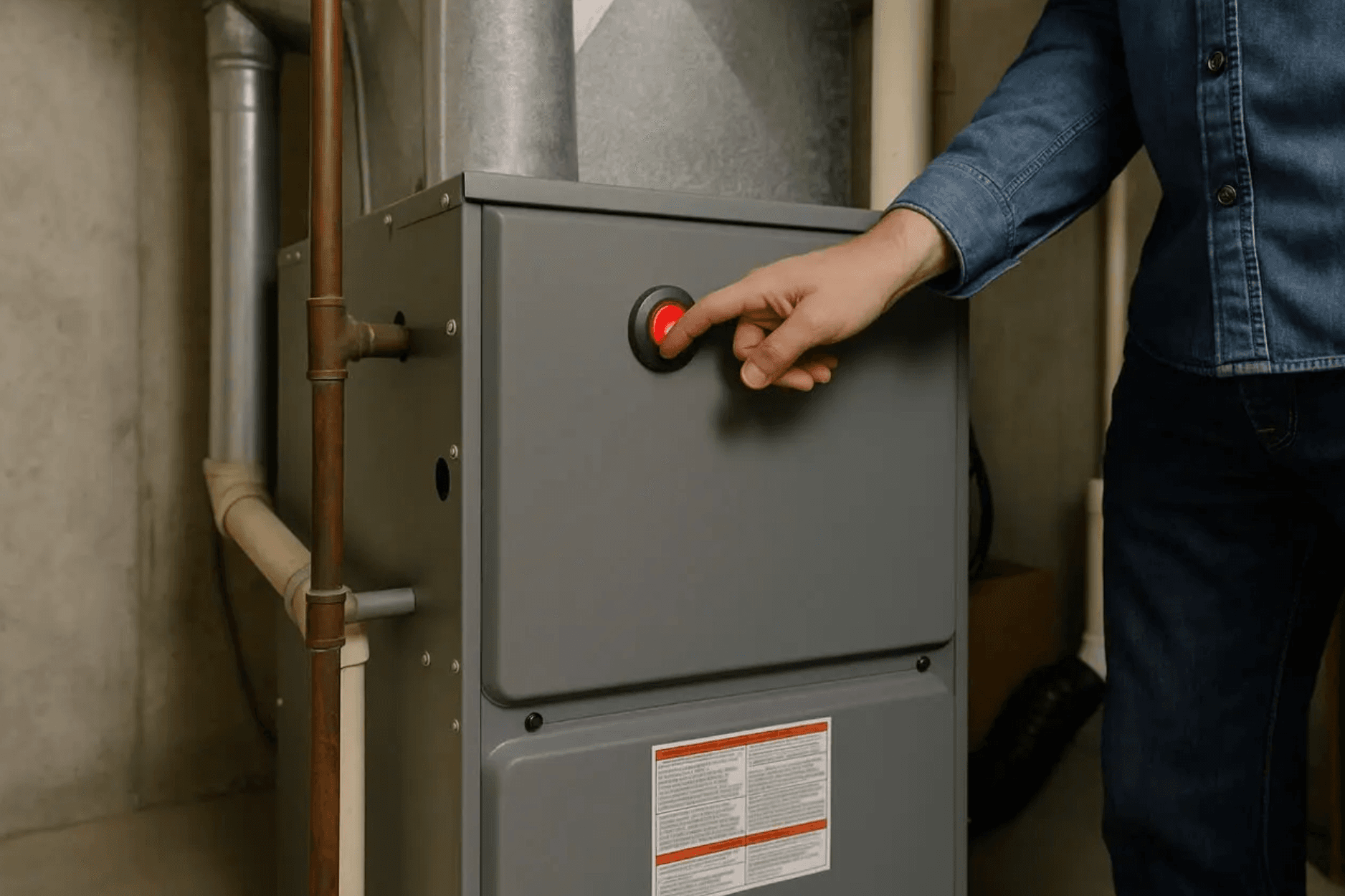
2.9. Turn Off Procedure
The furnace can be turned off using the service shut-off switch. While removing the cabinet panels and inspecting inside the unit goes beyond a standard visual inspection, switching the system off ensures safe observation of external components.
2.10. Cabinet Condition
Start by examining the furnace cabinet, including its panels and fasteners. Make sure the cabinet is secure and has no visible damage. There must be enough clearance around the unit for both combustion air and service access.
Most manufacturers recommend at least 3 inches (76 mm) of working space around the furnace. Always refer to the specific installation instructions provided by the manufacturer to confirm required clearances from combustible materials.
2.11. Blower Door Switch
The blower door switch is a built-in safety device. It automatically stops the blower fan when the compartment door is removed.
- Inspect the blower housing, fan blades, motor, belt (if present), and wiring.
- Look for dust buildup, loose connections, and ensure the fan rotates freely with minimal play.
- Listen to the blower during operation. Any unusual sounds or excessive vibration may signal a maintenance issue.
2.12. Control Board Inspection
The main control board, usually located inside the blower compartment.
- Inspect all wiring connected to the control board for fraying or damage.
- Ensure all electrical connections to the board are secure.
- Look for signs of burn marks, corrosion, or other damage on the board.
- Check the transformer for proper operation and secure mounting.
- Inspect the electrical junction box for loose wires or damage.
For replacement or upgrade, AZParts furnace circuit boards offer reliable alternatives. These boards are built to be compatible with many furnace models and include features that support efficient control and diagnostics.
2.13. Gas Shut-off Valve, Union, Sediment Trap, and Piping
The gas shut-off valve must be installed outside the furnace cabinet, within the same room as the furnace. It should be easy to reach, located no more than six feet from the furnace, and placed before any union or connector.
The union, which connects rigid gas piping sections, must be installed downstream of the shut-off valve. It should also be within six feet of the furnace and easily accessible.
The sediment trap, also called a drip leg, is designed to collect debris and moisture in the gas line. It must be installed downstream from the shut-off valve and as close as possible to the furnace’s gas inlet. While there is no required length, proper placement is essential for functionality.
When it comes to gas piping, only solid metal pipe is allowed to pass through the furnace cabinet. Flexible gas connectors are not permitted inside the cabinet. If a flexible connector is used, it must remain entirely visible and be located in the same room as the furnace—never routed through the furnace itself.
For systems using Corrugated Stainless Steel Tubing (CSST), proper bonding is critical for safety.
- Yellow-jacketed CSST must be electrically continuous and bonded to either the building's grounding electrode system or the lightning protection system. A bonding jumper (minimum 6 AWG copper or equivalent) should be connected to a metal pipe, pipe fitting, or CSST fitting.
- Black-jacketed CSST, which has an arc-resistant jacket, must also be bonded. It is considered properly bonded when connected to a furnace that is grounded through the appliance grounding conductor of the electrical circuit.
Gas shut-off valve must be properly installed and easily accessible (Source: Freepik)
2.14. Gas Valve Assembly
The gas valve assembly should be checked during normal operation using the thermostat. If the furnace has been converted from natural gas to liquefied propane (LP), a label must be present
2.15. Inducer Motor
Inspect the inducer fan motor and blower assembly while the furnace is running. It's important to note that natural draft furnaces are no longer manufactured due to their low energy efficiency and outdated design. They are generally considered past their expected service life.
2.16. Pressure Switches
Modern furnaces, especially two-stage models, may include more than one pressure switch. Each switch and its connecting hoses should be checked for proper installation and condition.
Modern furnaces may include more than one pressure switch (Source: Freepik)
2.17. Condensate Drainage System
Condensing furnaces, especially Category IV appliances, produce moisture as part of their operation. This moisture needs to be properly drained to avoid damage. You should inspect components including condensate trap, drainpipes, and overall drainage setup.
To prevent water damage:
- An auxiliary drain pan should be installed whenever water leakage could cause damage.
- A drain pan is not required when the furnace includes an automatic shut-off feature that stops the system during drainage failure.
For systems with a condensate pump, especially in uninhabitable areas like attics or crawlspaces:
- The furnace must shut off automatically if the pump stops working.
- The pump must also include an overflow shutoff function to provide added protection.
2.18. Burners & Manifold
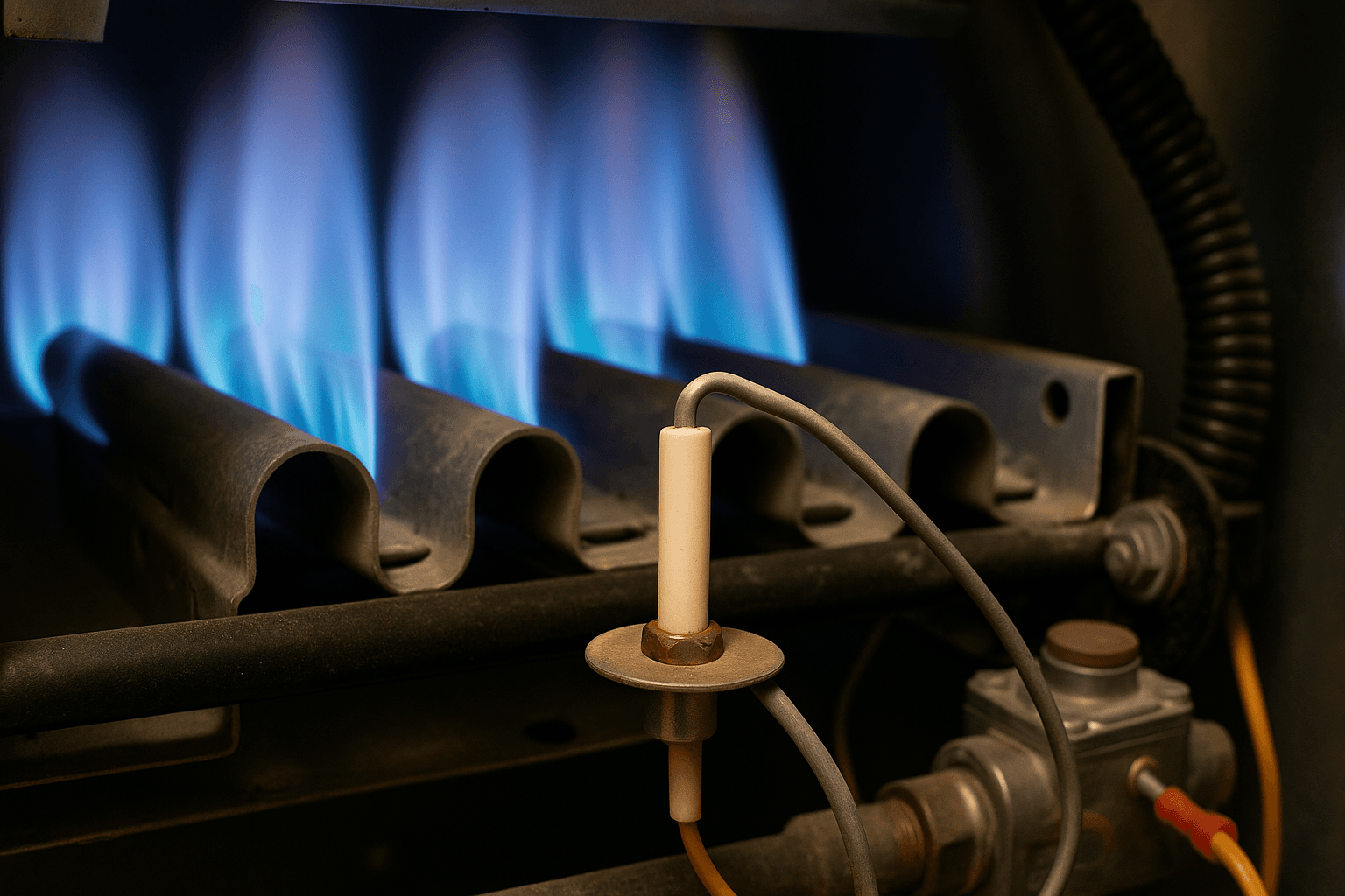
The manifold is a metal tube that distributes gas from the main gas valve to the burners. Most systems today use in-shot burners, which are common in modern furnaces.
- The entire burner assembly and manifold should be checked for signs of corrosion, moisture, or blockages.
- Inspect the burner cover panel for any visible damage or staining that might indicate leaks or rust.
- If the system includes air shutters, these should also be checked for proper positioning.
- The ignition sequence should be observed during normal operation using the thermostat.
- Finally, watch the burners as they turn on and fire. Look for smooth ignition and consistent flame behavior.
2.19. Ignitor & Flame Sensor Function
The ignitor, either a hot-surface ignitor or a spark ignitor, should be inspected for cracks, corrosion, or other visible damage.
- Check the associated wiring for wear or disconnection.
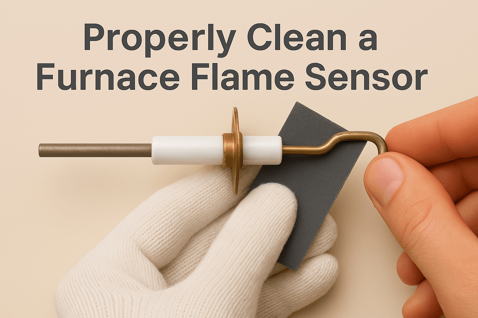
- Similarly, examine the flame sensor, which is a small metal rod near the burner, for dirt, corrosion, or looseness.
- Inspect the flame roll-out switches and their wiring.
During operation, listen for the clicking sound if a spark ignitor is in use. In hot-surface ignitors, a white-hot glow indicates activation, though white spots or cracks may signal damage.
The entire ignition source must be positioned at least 18 inches above the garage floor in accordance with safety guidelines, especially in areas considered part of or open to a garage space.
Watch the flame for unusual behavior, such as flickering, erratic movement, or changes in color while the blower fan is running. These signs may suggest issues with airflow, ignition timing, or burner alignment.
AZParts offers well-tested ignitor and flame sensor replacements that fit a wide range of furnace models. They’re built for dependable performance and meet industry standards for safety and ignition efficiency.
- 69W43 Furnace Flame Sensor
- The 2-Pack 62-23543-01 Furnace Flame Sensor
- The 4-Pack 62-23543-01 Furnace Flame Sensor
2.20. Limit Switches (High Limit, Rollout, etc.)
Temperature limit switches protect the furnace from overheating and ensure safe operation. Rollout switches, which detect flame escaping the burner area, are also important safety components and should be inspected carefully during routine checks.
- These switches, along with their wiring, should be checked for damage, corrosion, or loose connections.
2.21. Electrical Wiring & Connections
The electrical system of the furnace should be visually inspected for condition and safety. This includes all accessible components, wiring, and electrical connections.
- Look for signs of wear, corrosion, loose wires, or exposed conductors.
- Ensuring proper electrical integrity helps maintain safe operation and reduces the risk of faults during use.
2.22. Combustion Air Intake
Outdoor combustion air can be introduced using one or more permanent openings in the enclosure. Commonly, either a single opening 12 inches from the top of the space or two openings: one 12 inches from the top and one 12 inches from the bottom are used.
Additionally, where exhaust appliances like dryers or fans are present, makeup air must be provided to prevent negative pressure that could disrupt furnace operation.
As a general rule, at least 50 cubic feet of indoor combustion air should be provided per 1,000 BTU/h of furnace input. These air volume requirements ensure safe fuel combustion and the proper venting of flue gases.
Duct systems help ensure proper combustion air intake and balanced ventilation (Source: Freepik)
2.23. Air Distribution System (Ducts, Filters, Registers)
The air distribution system should be examined for overall cleanliness, integrity, and proper installation.
- Vibration isolators are often installed between the furnace and connected metal ducts to reduce noise and mechanical stress.
- Filters should be checked for dirt buildup. The filter compartment and access panel should seal properly to prevent air leaks.
- Ductwork must be inspected for signs of moisture, mold, damaged insulation, or loose sections. The exterior vapor barriers of insulated ducts should be intact, with no visible rips or gaps.
- Joints and seams should ideally be sealed with mastic, not just tape, as failing duct tape can lead to air leaks over time.
Return air must not be drawn from unsuitable locations such as the furnace room, attics, closets, bathrooms, kitchens, or garages, as these areas can compromise air quality and safety.
- Each habitable room should have a functioning supply register to deliver conditioned air.
- Grilles, registers, and diffusers should also be checked for dirt accumulation, blockages, or damage.
2.24. Verify start-up sequence and system response
The start-up sequence should be tested using the system’s standard operating control, typically the thermostat.
- Observe the furnace as it powers on to ensure each stage of ignition and heating occurs in the correct order.
- The ignitor should activate, followed by the burners and blower fan.
- The system should respond promptly and operate without delay, noise, or erratic behavior.
2.25. Monitor for proper safety shutdowns
Safety features such as limit switches, rollout sensors, and pressure switches must be monitored to confirm they shut down the system correctly in abnormal conditions. While intentionally triggering a fault is not part of a standard check, technicians should verify that the furnace includes these safety mechanisms and that no error codes or warning indicators are present during operation.
2.26. Check for flame sensor response and fan timing
The furnace flame sensor should be evaluated for proper response once the burners ignite. A working flame sensor will detect the flame and allow continued operation; failure to do so should result in a system shutdown.
Also, verify that the blower fan starts and stops according to the programmed fan timing, typically starting shortly after ignition and continuing for a short period after the burners shut off to maximize heat delivery.
The blower fan should start shortly after ignition and continuing for a short period after the burners shut off (Source: iStock)
3. FAQs about furnace inspection checklist
3.1. What is checked during a furnace inspection?
A furnace inspection typically includes checking the main components such as the burners, heat exchanger, blower motor, ignitor, flame sensor, gas valve, electrical connections, safety switches, condensate drainage system, and air filters. The inspector also verifies system response, proper airflow, and safe ignition and shutdown sequences.
3.2. What does a furnace inspection cover?
The inspection covers both safety and performance aspects of the furnace. This includes checking for gas leaks, signs of corrosion, electrical integrity, airflow issues, proper combustion air supply, duct condition, and ensuring the furnace operates within manufacturer and code guidelines.
3.3. How often should a furnace be inspected?
It’s recommended to have a professional furnace inspection at least once a year, ideally before the heating season begins. Regular inspections help prevent breakdowns, maintain efficiency, and ensure safe operation.
3.4. How do you check a furnace?
Checking all parts of furnace involves a step-by-step process:
- Turn on the thermostat to start the system
- Observe the ignition sequence and flame behavior
- Inspect components such as burners, ignitor, sensors, and limit switches
- Verify airflow through filters and ducts
- Check electrical connections and condensate drainage
- Confirm that safety devices are functional and the system shuts down properly when needed
Routine furnace inspections help prevent unexpected breakdowns and ensure your system runs safely and efficiently. While some maintenance tasks can be handled by homeowners, more technical checks should be performed by trained professionals using the right tools and safety precautions.
If your inspection reveals a worn-out or faulty component, AZParts offers a wide selection of reliable, high-quality furnace parts compatible with most models—trusted by technicians and built to last.
Contact Information:
- Address: 8 The Green, Ste A, Dover, Delaware 19901-3618, United States
- Email: support@azparts.com
Furnace
- 1. Furnace inspection checklist
- 2. Gas Furnace Inspection Checklist
- 2.1. Thermostat
- 2.2. Furnace Description & Location
- 2.3. Furnace Category (I, II, III, or IV)
- 2.4. Air Flow & Delta T
- 2.5 Venting (Exhaust & Flue System)
- 2.6. Protective Barrier
- 2.7. Lighting & Electrical Receptacle at Unit
- 2.8. Disconnect & Emergency Switch
- 2.9. Turn Off Procedure
- 2.10. Cabinet Condition
- 2.11. Blower Door Switch
- 2.12. Control Board Inspection
- 2.13. Gas Shut-off Valve, Union, Sediment Trap, and Piping
- 2.14. Gas Valve Assembly
- 2.15. Inducer Motor
- 2.16. Pressure Switches
- 2.17. Condensate Drainage System
- 2.18. Burners & Manifold
- 2.19. Ignitor & Flame Sensor Function
- 2.20. Limit Switches (High Limit, Rollout, etc.)
- 2.21. Electrical Wiring & Connections
- 2.22. Combustion Air Intake
- 2.23. Air Distribution System (Ducts, Filters, Registers)
- 2.24. Verify start-up sequence and system response
- 2.25. Monitor for proper safety shutdowns
- 2.26. Check for flame sensor response and fan timing
- 3. FAQs about furnace inspection checklist
Further Reading
Further Reading


